Neatware Company
An ISV for Mobile, Cloud, and Video Technologies and Software.
To build a complete shader, new shading languages for GPU must work along with a host programming language such as C/C++, although it is tedious to set large amount of parameters, C/C++ is the fastest on CPU. Other languages can also be used to build shaders. CUDA ("Compute Unified Device Architecture") is a C language extension for GPU programming. Unlike HLSL it removed many 3D components of a GPU language. CUDA had been developed by Nvidia and worked with GeForce 8 or later series. HLSL 5.0 for DirectX 11 added new GPGPU functions like CUDA that also worked for AMD's and Intel's GPUs. HLSL 5.1 supports DirectX 12 and later. Shader Model 6.0 has been presented and HLSL 6.0 is under deverlopment in 2016. Lately new OpenCL starts to replace CUDA as a multi-platform GPU language. New development from AMD's Mantle, a low-level graphics API for game developers to directly access functions of a GPU, is enabled HLSL to be a default shader language. The HSA (Heterogeneous System Architecture) along with Mantle may allow HLSL shaders to be GPU modules in the applications of High-Performance Computing and Real-time Video Processing. One thing needs to mentation is that Apple made C++ available for Shader Programming. References:
The Simplest ExampleA shader is consist of vertex shader and pixel shader. The stream of 3D model flows from application to the vertex shader, then to the pixel shader, finally to the frame buffer. a2v struct represents the data structure transferred from an application to a vertex shader, v2p from a vertex shader to a pixel shader, and p2f from a pixel shader to the frame buffer. Below program transforms a vertex's position into the position of clip space by view matrix.
  struct a2v {
    float4 Position : POSITION;
  };
Inside the HLSL function, struct a2v specifies a vertex structure that represents the data of a vertice.
  struct v2p {
    float4 Position : POSITION;
  };
struct v2p specifies a stream structure from vertex to pixel shader. Position is a four dimentional vector declared by float4. Furthermore, POSITION, called output semantic, indicates the initialized type of Position.
  void main(in a2v IN, out v2p OUT, uniform float4x4 ModelViewMatrix)
  {
    OUT.Position = mul(IN.Position, ModelViewMatrix);
  }
HLSL provides scalar data type like float and vector data type like float3. The scalar data types include bool with true or false value, int with 32-bit signed integer value, half with 16-bit floating point value, float with 32-bit floating point value, and double with 64-bit floating point value. An emulation will work while a GPU does not support a data type. A vector data type is declared as vector<type, size> where size is the dimension and type is the scalar component type. vector is a declaration of 4 dimensional float vector. Usually, we use float2, float3, and float4 for two, three, and four dimensional float vectors. float4x4 declares a float matrix type with 4 rows and 4 cols. A general matrix declaration has the form matrix<type, row_size, column_size>. A variety of dimensional declaration such as float3x4 is also acceptable. To access an element of matrix you can use m[i][j] or zero-based row-column position like _m00 as well as one-based row-column position like _11. You can think HLSL as a C language for GPU programming except there are no pointer, union, bitwise operations, and function variables. There are no goto, switch, recursive function in HLSL as well. However HLSL adds vector data type, build-in constructor, swizzling and masking operators. HLSL standard library includes mathematical functions and texture processing functions. The function overloading has been used to unify the operations of different vectors. vs_1_1 dcl_position v0 m4x4 oPos, v0, c0 mov oD0, c4 This asm program is the compiled code of the simplest HLSL example. First, vs_1_1 specifies the version of vertex shader as 1.1. Second, dcl_position v0 declares that v0 is a position register. The third statement declares a matrix multiply with source variable register v0 and constant register c0 where oPos represents the destination position register. Finally, the last statement moves the value of register c4 to register oD0. Usually, vN represents input register and oXXX represents output register in the assembly vertex shader language. Add Diffuse ColorIn this example we add COLOR component as the diffuse color.
float4x4 ModelViewMatrix; ModelViewMatrix is declared as a global variable. Its value is assigned by the host program running on CPU. By using global variable declaration instead of the uniform declaration, the HLSL code may become more understandable.
  struct a2v {
    float4 Position : POSITION;
    float4 Color    : COLOR0;
  };
a2v structure declares the data structure transferred from application vertex shader. Note POSITION and COLOR0 are input semantics that link the vertex buffer of the application to the vertex shader. Vertex shader input semantics include POSITIONn for Position, BLENDWEIGHTn for Blend weights, BLENDINDICESn for Blend indices, NORMALn for Normal vector, PSIZEn for Point size, COLORn for Color, TEXCOORDn for Texture coordinates, TANGENTn for Tangent, BINORMALn for Binormal, and TESSFACTORn for Tessellation factor.
  struct v2p {
    float4 Position : POSITION;
    float4 Color    : COLOR0;
  };
v2p structure declares the data structure transferred from vertex shader to pixel shader. Vertex shader output semantics include POSITION for Position, PSIZE for Point size, FOG for Vertex fog, COLORn for Color, and TEXCOORDn for texture coordinates.
  void main( in a2v IN, out v2p OUT )
  {
    OUT.Position = mul(IN.Position, ModelViewMatrix);
    OUT.Color    = IN.Color;
  }
In this example Color component specifies the diffuse color from application. It simply copies the Color from the IN to OUT in the main function. Diffuse and Specular
  float4x4 ModelViewProj;
  float4x4 ModelViewIT;
  float4 LightVec;
these are global variables.
  struct a2v {
    float4 Position : POSITION;
    float4 Normal   : NORMAL;
  };
Normal item is added for color computing.
  struct v2p {
    float4 Position : POSITION;
    float4 Color    : COLOR0;
  };
color outputs to pixel shader.
  void main( in a2v IN, out v2p OUT )
  {
input parameters include view project matrix ModelViewProj, view inverse transpose matrix ModelViewIT, and light vector LightVec.
OUT.Position = mul(IN.Position, ModelViewProj);
multiply position with view project matrix
     float4 normal = mul(IN.Normal, ModelViewIT);
     normal.w = 0.0;
     normal = normalize(normal);
     float4 light = normalize(LightVec);
     float4 eye = float4(1.0, 1.0, 1.0, 0.0);
     float4 vhalf = normalize(light + eye);
transform normal from model-space to view-space, store normalized light vector, and calculate half angle vector. float4(1.0, 1.0, 1.0, 0.0) is a vector constructor to initialize vector float4 eye. .xyzz, a swizzle operator, sets the last component w as the z value.
     float diffuse = dot(normal, light);
     float specular = dot(normal, vhalf);
     specular = pow(specular, 32);
calculate diffuse and specular components with dot product and pow function.
     float4 diffuseMaterial = float4(0.5, 0.5, 1.0, 1.0);
     float4 specularMaterial = float4(0.5, 0.5, 1.0, 1.0);
set diffuse and specular material.
     OUT.Color = diffuse*diffuseMaterial + specular*specularMaterial;
  }
add diffuse and specular components and output final vertex color. To better understand a swizzle operator, readers can compare cross definition
  float3 cross( float3 a, float3 b ) {
    return float3( a.y*b.z - a.z*b.y, a.z*b.x - a.x*b.z, a.z*b.y - a.y*b.z );
  }
and its swizzle implementation
  float3 cross( float3 a, float3 b ) {
    return a.yzx*b.zxy - a.zxy*b.yzx;
  }
Draw Texture
  float4x4 ModelViewProj;
  float4x4 ModelViewIT;
  float4 LightVec;
global variables
  struct a2v {
    float4 Position : POSITION;
    float2 Texcoord : TEXCOORD0;
    float4 Normal   : NORMAL;
  };
add new Texcoord component as texture coordinate with TEXCOORD0.
  struct v2p {
    float4 Position  : POSITION;
    float2 Texcoord  : TEXCOORD0;
    float4 Color     : COLOR0;
  };
add Texcoord in output
  void main( in a2v IN, out v2p OUT )
  {
    OUT.Position = mul(IN.Position, ModelViewProj);

     ... same as the above example
set texture coord
     OUT.Texcoord = IN.Texcoord;
  }
the code is the same as the above example except that the texture coord copy is added. Pixel Shader
  float brightness;
  sampler2D tex0;
  sampler2D tex1;
brightness is the value to control the bright of light. Both tex0 and tex1 are the sampler of the textures.
  struct v2p {
    float4 Position  : POSITION;
    float2 Texcoord0 : TEXCOORD0;
    float2 Texcoord1 : TEXCOORD1;
    float4 Color     : COLOR0;
  };
v2p declares a struct type that transfers data from vertex shader to pixel shader. It is the same as the struct in vertex shader. The input semantics of pixel shader can be COLORn for Color or TEXCOORDn for Texture coordinates. Although the struct v2p must be the same as the v2p in the vertex shader, the item Position can not be read in the pixel shader, because it is not binded by the input semantics of the pixel shader.
  struct p2f {
    float4 Color : COLOR0;
  };
p2f declares output data structure and OUT is the output object. The output semantics of pixel shader can be COLORn of Color for render target n and/or DEPTH for Depth value.
  void main( in v2p IN, out p2f OUT )
  {
Constant parameter brightness has a float type. sampler2D specifies a 2D texture unit. When you plan to access a texture you must use sampler with an intrinsic function. A sampler can be used for multiple times.
    float4 color = tex2D(tex0, IN.Texcoord0);
    float4 bump = tex2D(tex1, IN.Texcoord1);
fetch texture color and bump coordinate for further computing of bump effect. tex2D is an texture sampling intrinsic function of HLSL. It generates a vector from a texture sampler and a texture coordinate.
    OUT.Color = brightness * IN.Color * color;
  }
the code multiples brightness, IN.Color and color to generate output RGBA color vector. Bump Mapping and Per-Pixel Lighting
Per-Pixel lighting provides an efficient and attractive method to render a surface. Standard lighting model consists of P for vertex position, N for unit normal of vertex, L for unit vector from light source to vertex, V for unit vector from vertex to view position, and R for unit reflection vector.
  sampler2D tex0;
  sampler2D tex1;
This is the bump mapping pixel shader with HLSL. v2f is the structure from vertex to pixel. Position is the float4 vector, Diffuse is the diffuse color component, and texcoord0, texcooord1 are texture coordinates respectively.
  struct v2p {
    float4 Position  : POSITION;
    float2 Texcoord0 : TEXCOORD0;
    float2 Texcoord1 : TEXCOORD1;
    float4 Diffuse   : COLOR0;
  };
p2f is the final output data structure.
  struct p2f {
    float4 Color : COLOR0;
  };
main function has one input from vertex shader and two texture samplers. OUT is an object of p2f.
  void main( in v2p IN, out p2f OUT )
  {
fetch base Color and Normal
     float4 Color = tex2D(tex0, IN.Texcoord0);
     float4 Normal = tex2D(tex1, IN.Texcoord1);
set final color
     OUT.Color = Color*dot(2.0*(Normal-0.5), 2.0*(IN.Diffuse-0.5));
  }
Following code is the vertex shader with hlsl. float4x4 ModelWorld; float4x4 ModelViewProj; float4 vLight; float4 vEye; float4 vDiffuseMaterial; float4 vSpecularMaterial; float4 vAmbient; float power; global variables
  struct a2v {
    float4 Position : POSITION;
    float2 Texcoord : TEXCOORD0;
    float4 Normal   : NORMAL;
    float4 Tangent  : TANGENT;
  };
  struct v2p {
    float4 Position  : POSITION;
    float4 Color     : COLOR0;
    float2 Texcoord0 : TEXCOORD0;
    float2 Texcoord1 : TEXCOORD1;
  };
define main function, get position
  void main( in a2v IN, out v2p OUT )
  {
    OUT.Position = mul(IN.Position, ModelViewProj);
transform normal from model-space to view-space
    float4 tangent = mul(float4(IN.Tangent.xyz,0.0),ModelWorld);
    float4 normal = mul(float4(IN.Normal.xyz,0.0),ModelWorld);
    float3 binormal = cross(normal.xyz,tangent.xyz);
Position in World
float4 posWorld = mul(IN.Position, ModelWorld);
get normalize light, eye vector, and half angle vector
    float4 light = normalize(posWorld-vLight);
    float4 eye = normalize(vEye-light);
    float4 vhalf = normalize(eye-vLight);
transform light and vhalf vectors to tangent space
    float3 L = float3(dot(tangent, light), dot(binormal, light.xyz), dot(normal, light));
    float3 H = float3(dot(tangent, vhalf), dot(binormal, vhalf.xyz), dot(normal, vhalf));
calculate diffuse and specular components
    float diffuse = dot(normal, L);
    float specular = dot(normal, H);
    specular = pow(specular, power);
combine diffuse and specular contributions and output final vertex color, set texture coordinates, and return output object.
    OUT.Color = 2.0*(diffuse*vDiffuseMaterial
              + specular*vSpecularMaterial) + 0.5 + vAmbient;

    OUT.Texcoord0 = IN.Texcoord;
    OUT.Texcoord1 = IN.Texcoord;
  }
Image Processing (1): Sobel Edge Filter
  float Brightness;
  sampler2D tex0;
global variables
  struct v2p {
    float4 Position   : POSITION;
    float2 Texcoord   : TEXCOORD0;
    float4 Color      : COLOR0;
  };

  struct p2f {
    float4 Color      : COLOR0;
  };
main function includes a vertice struct as input, a float parameter as brightness control, and a 2D texture sampler. The return value has float4 type with the semantic COLOR0. void main( in v2p IN, out p2f OUT )
{
const specifies the constants. The c[NUM] is a float2 constant array. Notes its initialization is convenience like C language. col[NUM] is a variable array of type float3 with NUM elements. int i declares the i as integer. These usage is effective for pixel shader 2.0 or later. const int NUM = 9;
const float threshold = 0.05;
const float2 c[NUM] = {
float2(-0.0078125, 0.0078125),
float2( 0.00 , 0.0078125),
float2( 0.0078125, 0.0078125),
float2(-0.0078125, 0.00 ),
float2( 0.0, 0.0),
float2( 0.0078125, 0.007 ),
float2(-0.0078125,-0.0078125),
float2( 0.00 , -0.0078125),
float2( 0.0078125,-0.0078125),
};
float3 col[NUM];
int i;
it stores the samples of texture to col array.
    for (i=0; i < NUM; i++) {
      col[i] = tex2D(tex0, IN.Texcoord.xy + c[i]);
    }
now we start to compute the luminance with dot product and store them in lum array.
    float3 rgb2lum = float3(0.30, 0.59, 0.11);

    float lum[NUM];
    for (i = 0; i < NUM; i++) {
      lum[i] = dot(col[i].xyz, rgb2lum);
    }
Sobel filter computes new value at the central position by sum the weighted neighbors.
    float x = lum[2]+  lum[8]+2*lum[5]-lum[0]-2*lum[3]-lum[6];
    float y = lum[6]+2*lum[7]+  lum[8]-lum[0]-2*lum[1]-lum[2];
show the points which values are over the threshold and hide others. Final result is the product of col[5] and edge detector value. Brightness adjusts the brightness of the image.
float edge =(x*x + y*y < threshold)? 1.0:0.0;
final output
    OUT.xyz = Brightness * col[5].xyz * edge.xxx;
    OUT.w = 1.0;
  }
Image Processing (2): Mask
sampler2D tex[3];

struct v2p {
	float4 Position  : POSITION;
	float4 Color     : COLOR0;
	float2 Texcoord0 : TEXCOORD0;
	float2 Texcoord1 : TEXCOORD1;
	float2 Texcoord2 : TEXCOORD2;
};
These are the texture samplers and struct
void main(in v2p IN, out float4 OUT : COLOR)
{
	float Brightness = 1.2345;
	float alpha = 0.96;

	float3 color0 = tex2D(tex[0], IN.Texcoord0);
	float3 color1 = tex2D(tex[1], IN.Texcoord1);
	float3 mask   = tex2D(tex[2], IN.Texcoord2);
The HLSL sample code is quite simple for the formula. OUT.rgb = Brightness *(color0 * mask + color1 * (1.0-mask)); OUT.a = 1.0; } Shader Model 3.0
sampler2D tex0;
sampler2D tex1;
texture sampler
struct v2p {
  float4 Position   : POSITION;
  float4 Color      : COLOR0;
  float2 Texcoord0  : TEXCOORD0;
  float2 Texcoord1  : TEXCOORD1;
};
vertex shader input
void main(in v2p IN, out float4 OUT : COLOR)
{
pixel shader main function. float Brightness = 1.1; int i, j; float2 tc = IN.Texcoord0; float b[5]; float2 s[5]; float3 col[5]; define variables and arrays. float3 rgb2lum = float3(0.30f, 0.59f, 0.11f); s[0] = float2( 0.0f, 0.0f ); s[1] = float2( 0.0f, 0.0078125f ); s[2] = float2( 0.0078125f, 0.0f ); s[3] = -s[1]; s[4] = -s[2]; set convertible constants
  for (i=0; i<5; i++) {
    col[i] = tex2D(tex0, tc + s[i]);
    b[i] = dot(col[i].xyz, rgb2lum);
  }

  float flag[4];
  float r;
  for (i=0; i<4; i++) {
    r = -1.0f;
    for (j=0; j<5; j++) {
      r += step(b[i], b[j]);
    }
    flag[i] = r;
  }
compute the values of flag array.
  OUT.xyz = Brightness * (( flag[0] == 2.0 ) ? col[0] :
            (( flag[1] == 2.0 ) ? col[1] :
            (( flag[2] == 2.0 ) ? col[2] :
            (( flag[3] == 2.0 ) ? col[3] : col[4] ))));
  OUT.w = 1.0;
}
Final output Video Mixing (1): Vertex Shader
  float4x4 WorldViewProj;
  float4x4 WorldViewIT;
  float4 LightPos;
  float4 EyePos;
  float fTime;
WorldViewProj is the transform matrix from model space to clip space. WorldViewIT is the transform matrix from model space to view space. LightPos is the light position in model space. EyePos is the eye position in model space. These global variables are reserved for later using. fTime is the application time that can be used to control effects in timeline.
  #define NUMTEXCOORD 4

  struct a2v {
	  float3 Position              : POSITION;
	  float  Diffuse               : COLOR;
	  float2 TexCoord[NUMTEXCOORD] : TEXCOORD0;
  };
This is the input structure from application to the vertex program (a2v). Position is the position in model space. Diffuse specifies the diffuse color. TexCoord specifies texture coordinates where video streams are represented as textures. The number of textures NUMTEXCOORD is dependent on the graphic hardware. Four is the minimum support and some cards can sample upto 16 textures.
struct v2p {
	float4 Position	             : POSITION;
	float4 Color                 : COLOR0;
	float2 Texcoord[NUMTEXCOORD] : TEXCOORD0;
};
This is the structure from vertex shader to pixel shader (v2p).
void main(a2v IN, out v2p OUT)
{
	OUT = (v2p) 0;
	OUT.Position = mul(float4(IN.Position, 1.0f), WorldViewProj);

	for (int i=0; i < NUMTEXCOORD; i++) {
		OUT.Texcoord[i] = IN.TexCoord[i];
	}
}
The main program transforms the position from model space to clip space. Then copy the texture coordintates to output. Video Mixing (2): Pixel Shader
Ring wipe defines a ring in the center of the first picture. The area between the inner circle and the outer circle is the mixing of two pictures by alpha values that is decided by the distance to the center. The area inside the inner circle is belong to the first picture. And the area outside the outer circle is belong to the second picture.
sampler2D tex[2];

struct v2p {
	float4 Position	: POSITION;
	float4 Color : COLOR0;
	float2 Texcoord[2] : TEXCOORD0;
};
sampler2D defines texture array that represents the video streams. v2p is the struct of stream from vertex shader to pixel shader.
void main(in v2p IN, out float4 OUT : COLOR)
{
	float Brightness = 1.2343;
	float len = 0.3;
	float a = 0.2;
	float b = a+len;
	float2 center = float2(0.5, 0.5);
	float3 result;
Brightness is the variable for brightness of light. a and b are the radius of inner and outer circle respectively. len is the width of the ring. And the center is the centric coordinate of the ring. result represents the result of the value of effect. float3 color0 = tex2D(tex[0], IN.Texcoord[0]); float3 color1 = tex2D(tex[1], IN.Texcoord[1]); float2 point = IN.Texcoord[0]; color0 and color1 are sampled color value from the first picture and the second picture respectively. point is the current coordinate value.
	float dist = distance( point, center );
	if ( dist < a) {
		result = color0;
	} else if (dist > b) {
		result = color1;
	} else {
		result = lerp(color0, color1, saturate((dist-a) / len));
	}
This is the kernel of the algorithm. distance is the build-in HLSL function. saturate function converts dist value from [a, b] to [0, 1]. lerp is the build-in function for linear interpolation. OUT.rgb = Brightness * result; OUT.a = 1.0; } OUT is the last result. Ring wipe transform is one of the most interesting transforms because the position and size of a ring can be variant. Furthermore, many ring wipes can be applied on different center of a shader. At this stage the SM3.0 will be very helpful. Who has said that software was always lagged hardware? FX Effects
A detailed article about the FX effects and the use of effects in Ladybug Mixer * is here. |
 High Level Shading Language (HLSL), a programming language for Graphic Processing Unit (GPU) in DirectX 9/10/11, supports the shader construction with C-like syntax, types, expressions, statements, and functions.
 main is a vertex shader function name. void means that this function will return nothing. The input parameter IN is specified by in modifier and struct a2v. Similarly, the output parameter OUT is specified by out modifier with the type v2p. In addition, float4x4 declares a matrix ModelViewMatrix. The uniform modifier indicates that the value of the matrix is a constant assigned by external program. Finally, this simplest vertex shader outputs the multiplication of the vector Position and the matrix ModelViewMatrix. While IN.Position is the left parameter of mul, it is considered as a row vector. Otherwise it is considered as a column vector.
 This is a little bit more complicated example shown the implementation of diffuse and specular color.
 Now we are going to show how to add texture on a surface
 Pixel shader completes the computing of pixels.
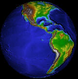 This example demonstrates the use of Vertex and Pixel shaders for bump mapping. Bump mapping is a multitexture blending technique used to generate rough and bumpy surfaces. The data of Bump map (or normal map) are stored as a texture. Bump mapping includes an environment map and a bump data.
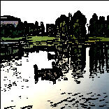 This program shows the implementation of Sobel edge filter with a HLSL pixel shader. In the similar way we can implement many image filters in pixel shader.
 A well known example of three media streams is the mask transform. A mask is a black and white image. Two media streams and a mask picture are the inputs. The effect is the sum of the first stream multiples the mask and the second stream multiples the negative of mask. Therefore, two streams are showed in the areas distinguished by the shape of the mask.
 There are many posts about Shader Model 3.0. Following HLSL code can not be compiled with Shader Model 2.0 but Shader Model 3.0 should. Read the error message that will show a difference between SM2 and SM3.
![]() Copyright ©2004-2015 Neatware. All Rights Reserved.
Copyright ©2004-2015 Neatware. All Rights Reserved.